ADS software is a useful tool for designers, engineers, and businesses to rapidly design and manufacture high-quality components and systems.
This software makes it easy to design and simulate parts, no matter how complex. Moreover, the intuitive interface makes it easy to learn and adapt.
ADS is revolutionizing the world of circuit and system design in electronics, automotive, and other industries with rapid adoption of this unique solution with ready-to-use capabilities.
So, let’s learn more about ADS software and see how it can help you.
What is ADS?
Advanced Design System (ADS) is the most advanced electronic circuit design, simulation, and automation software developed by PathWave Design, a Keysight Technologies company.
ADS software provides an integrated environment for designing RF electronic systems such as wireless networks, cellular telephones, satellite communications, pagers, high-speed data links, and radar systems. Its first release appeared in 1985 and was named Microwave Design System (MDS). ADS was introduced in 2016 with improvements in speed, performance, and design flexibility.
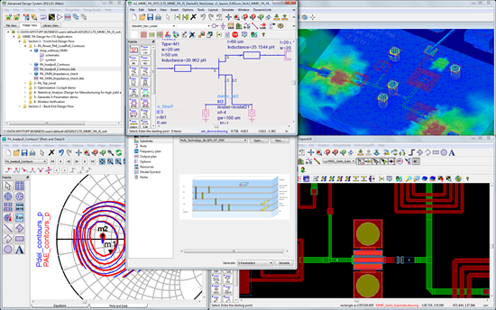
Designers can use ADS at every step of the design process, from schematic capture, design rule checking, and layout to electromagnetic simulation and time-domain and frequency-domain circuit simulation. In this way, designers can easily evaluate and optimize RF design features without changing tools or systems.

Features of ADS
Some of the features of ADS are:
- Design Templates: ADS provides integrated design support through convenient templates that get you started quickly, without having to spend a lot of time creating each design element from scratch.
- Component Library: Get an extensive library of components where you can find the parts you need to add to your design. This also saves a lot of time. All you need to do is browse through the various components and select the ones you need for your design.
- Automatic synchronization: ADS allows you to automatically synchronize layouts and visualize the actual layout while designing the schematic.
- Flexibility: A complete desktop flow allows you to design more successfully. Additionally, we create designs according to current standards, incorporating industry-leading designs and foundry designs. You can also use X-parameters to model nonlinear designs. For your information, X-parameters is a registered trademark of Keysight in the US, Japan, EU, and other regions of the world. X-parameters includes equations and forms to help you design.
- Display optimization: Optimize your data and cockpit displays to create what you’ve always dreamed of creating. It also helps increase yield by allowing you to visualize your designs, easily modify them, and create high-quality designs without multiple iterations.
- Integration: ADS software can be integrated with PathWave’s electromagnetic simulator. This gives you a clear 360-degree view of your design and also allows you to determine if it’s working as expected. As a result, you can find areas for improvement and make your design more effective.
- Management: ADS software contains all the data related to the design, components, and complete system you aim to create. It also makes it easier to manage your workspace and accelerate production. Workspaces can also be shared and managed by your entire team.
Advantages of ADS
The benefits of using ADS software are:
Provides design confidence
Accurate data from ADS allows teams to visualize and determine whether a design meets the required specifications. ADS software data analysis and visualization includes charts, diagrams, and graphs that help you clearly view and analyze data and make conclusions and corrections. Additionally, once design flaws are known, they can be easily corrected, increasing the reliability of the design.
Faster production
Use helpful templates, wizards, and design guides to accelerate your design and get it into production quickly. The entire design flow includes schematics, circuits, layout, electrothermal simulation, electromagnetic simulation, and more.
Even if your team is new to this software, it won’t be difficult to adapt to it. Easily design and improve all components and move them into production faster. The result is faster time to market.
Overcoming high-speed design challenges
As speed and frequency increase, power and signal integrity at printed circuit boards (PCBs) become more critical, and losses in transmission lines can lead to electronic device failure.
Therefore, modeling interconnects, traces, and vias is critical to accurately simulating a PCB. That’s why Keysight helps improve high-speed link performance in PCB designs through customized electromagnetic simulators for signal and power integrity analysis and integrated circuit design.
The result is a perfect design for each component of the system and the ability to manufacture them without much thought.
Improve design confidence
Reliability and efficiency are two major considerations when designing and manufacturing components and machines.
Systems such as solar inverters, electric vehicles, and power supplies require efficient design. Therefore, companies are looking for ways to improve the efficiency and reliability of power devices even during the design stage. Materials such as gallium nitride and silicon carbide can help with this. Keysight’s ADS allows you to model switch-mode power supplies and advanced materials to optimize your design for maximum efficiency.

ADS application
The areas where ADS software can be used are described below.
circuit simulation
ADS 2016 is a powerful software that enhances the harmonic balance engine and improves the accuracy, convergence, and speed of circuit simulators. It also provides better DC annotation, helping speed production even with complex designs.
Additionally, Linux and Windows support for electrothermal simulation increases the system’s ease of use for almost any designer. You can also run simulations on multiple cloud-based servers and take advantage of enhanced speed and scalability.
silicon RFIC
Keysight’s ADS enables high-density and intelligent interconnection of circuit design systems such as radio frequency integrated circuits (RFICs), laminates, antennas, monolithic microwave integrated circuits (MMICs), modules, wafer-level packaging, and PCBs. Integration helps reduce hardware failures and associated costs. 3D structure.
ADS also helps simulate EVM for optimization and tuning that helps validate industry-level wireless standards such as automotive radar, 5G, and WiFi. With comprehensive and rigorous amplifier stability analysis, ADS replaces traditional techniques to enhance amplifier stability under non-environmental conditions. Straight and linear condition.
Validating the layout
New features and enhancements introduced to ADS software make layouts faster, more robust, and more intuitive. Improvements have been made to manufacturing grid control and checking, ground nets, 3D viewer, connections and highlighting, layout mapping to schematic net names, and importing .brd files for EM simulations.
True arcs for accurately drawing or editing spirals and curved traces, automatic GDSII export/import to avoid user errors, and bulk editing of various structures such as shapes, traces, pads, and vias on the same net We provide. You can also use Design Rule Checking (DRC) to check density in local areas.
electric heating
ADS provides accurate SAW filter design and graphene modeling. You can use one thermal model with different imported designs to improve interoperability flow.
power integrity
ADS offers signal integrity-focused EM simulation for complex and high-precision PCB applications with PIPro, a power integrity-focused EM simulator for analyzing power distribution networks .
We also provide:
- New sparse direct solver enables 40% faster simulations even for complex structures
- Reduce simulation time with mesh cache
- Cached GUI of component models allows for easy deletion or selection
- Multiple VRMs in a single DC IR drop simulation
How do I create designs using ADS?
Creating your first design using ADS software can seem daunting. But if you know the basics, it becomes easier, and after that you can keep practicing to reach the advanced stage.
A quick and detailed explanation of how to create your first design in ADS, then simulate and plot the results.
Creating a schematic
First, create a schematic design for the part or component you need. For example, suppose you want to create a lowpass filter. For this, we first need to add components such as resistors.
ADS has a component library that you can use to find pre-built components and add them to your design. It’s a huge time saver compared to creating one from scratch. A variety of components are available to make your design quick and easy, including resistors, capacitors, wires, links, data items, measurement sources, and simulation controllers.
These components are also categorized into “palettes”. Drop-down menus make it even easier to switch between palettes. Palette names are self-explanatory, making them easy to discover and place in your design environment. For example, if you are looking for resistors, capacitors, or inductors, you can find them under Bulk Components. If you are having trouble finding a component, you can view the component list alphabetically.
Place components
Once you have found the desired component, such as a resistor, you can place it on the schematic. When you select a component, it remains on the cursor. Therefore, you can abort the placement of the same component by pressing the ESC key. After this, you need to change the parameters of the component, which are initially defined by default. To do this, click on the default value and rewrite the value based on your requirements. However, the value may not be displayed by default. To do this, you can double-click on that component to see other properties that you want to change.
You can then repeat the same steps when adding another component, such as a capacitor or inductor, from the palette list. You can also change the orientation by rotating the component 90 degrees. To do this, find the option from the toolbar. Additionally, you can also change the unit prefix.
Keysight’s ADS software is flexible and easy to use with drag options. If you want to make the schematic more clear, you can move it by dragging it. This does not change your connection.
Sync your designs
For a schematic design to be meaningful, you must define the connections between components and how the components are placed within the design. Helps you sync your designs.
For example, you can connect a capacitor to ground. To do this, select “Ground” from the toolbar. You can also insert wires to connect various components. This is useful for measuring output voltage.
simulation
For simulation, a simulation controller is required to define the objectives of the simulation. You can find different types of simulation controllers, including S-parameter, DC-AC, load-pull, and harmonic balance. Running simulations is not difficult with ADS software.
For example, if you want to run the simulation as an AC, go to the Simulation AC palette and find the AC Simulation Controller.
No matter which simulation controller you select, a gear icon will appear. Therefore, select any simulation controller and change the settings based on your simulation requirements.
The simulation phase requires various elements such as source components and labels. Once you have selected your source component, you need to place it into your simulation environment. As before, change the values for the default selected component set.
However, if you want to easily calculate voltage without using probe components, you can select “Label”. If you use a label, such as a wire pin label, define the net name and add it where you want the voltage to be calculated.
In this way, you can create fully functional circuits that can be simulated right away. Therefore, use the F7 hotkey on your keyboard or toolbar to start the simulation. Now you can see how all the components interact and how the circuit works.
plot
When you run the simulation, a page appears where you can add equations and plots.
There are many different types of plots and charts to choose from, including Smith charts, polar plots, and rectangular plots. There is an element called the “vout” variable (spelled “v out”), which is the measurement from the placed label.
Example: I selected a rectangular plot.
Now we need to define the x and y axes and start plotting.
Here “vout” becomes the y-axis of this plot, and a simulation controller, such as an AC simulation controller, sets frequency to the x-axis of the plot. You can now view your data using this plot in ADS.
conclusion
ADS software makes it easy to design parts and systems, both simple and complex. It not only offers unique features and functionality, but is also easy to use for engineers and designers.
So if you’re looking for a good software solution to design PCBs, circuits, etc., give it a try. We also offer a free trial that you can use to see if it can help you solve your design or simulation challenges.


![How to set up a Raspberry Pi web server in 2021 [Guide]](https://i0.wp.com/pcmanabu.com/wp-content/uploads/2019/10/web-server-02-309x198.png?w=1200&resize=1200,0&ssl=1)

")


 in Roblox")
")


")


")


")
